About Klaus Petersen

I like to create magical things, especially projects related to new technologies like augmented and virtual reality, mobile robotics and MEMS-based sensor networks. I code in C(++) and Python, trying to keep up with my very talented colleagues :-)

IMUcore Customizable Sensor Fusion Solution

Introducing IMUcore

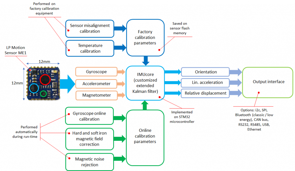
IMUcore customizable sensor fusion solution is the central algorithm working inside all LP-RESEARCH IMUs. It collects orientation data from several sources and combines them into fast and drift-free tilt and direction information. To work with any type of MEMS sensor, various online and offline calibration methods have been implemented to guarantee high quality data output. The algorithm is very versatile and performance-saving. It can be implemented on embedded MCUs with minimum power consumption.

IMUcore is now available as a solution from LP-RESEARCH. Please contact us here for more information or a price quotation.

Overview of embedded sensor fusion in LPMS devices

Sensor Fusion Filter Overview

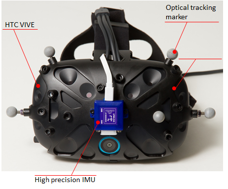
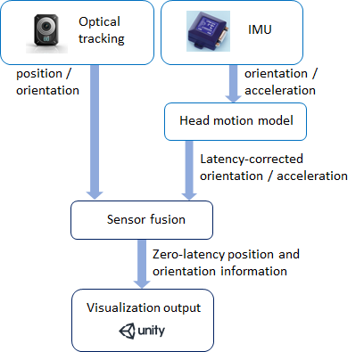
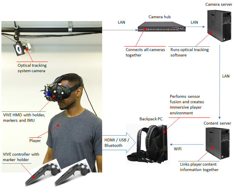
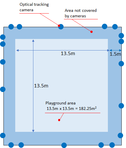
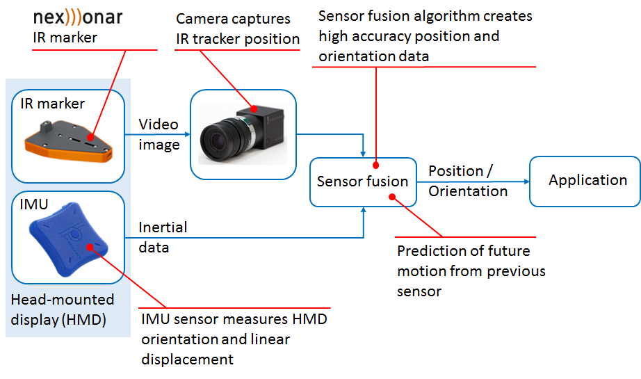
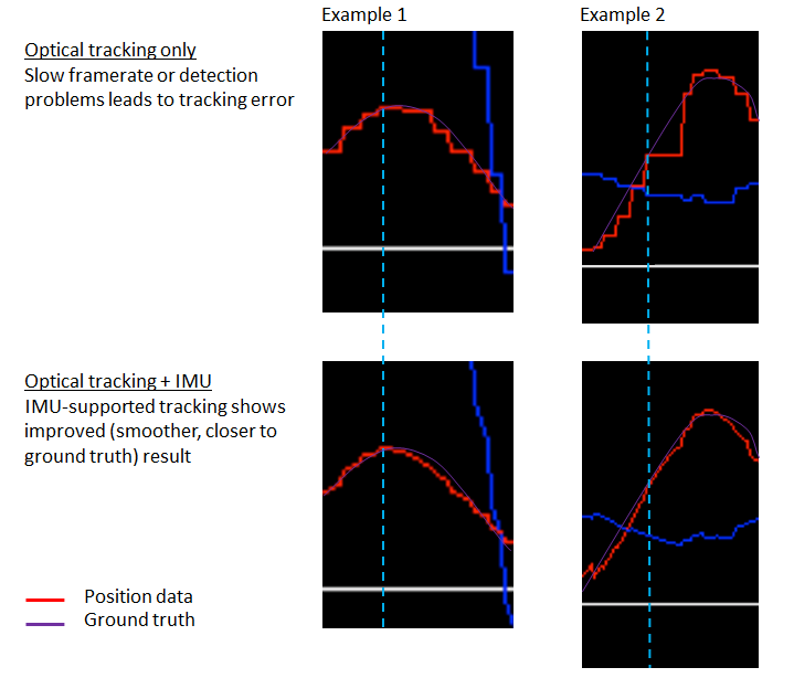
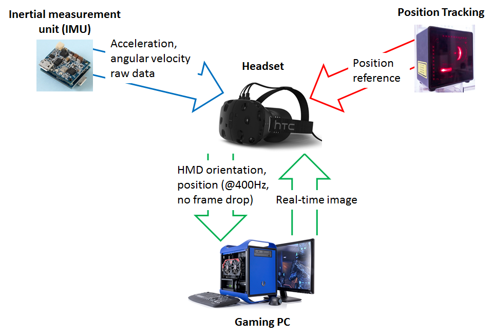
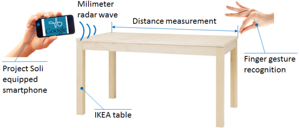
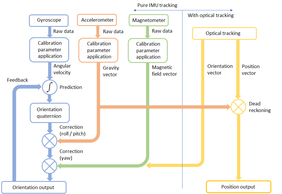
The IMUcore customizable sensor fusion solution uses gyroscope data as basis information to calculate orientation. Errors introduced through measurement noise are corrected by accelerometer and compass data. Optionally the sensor fusion can be extended with an optical (or other) tracking system to additionally provide position information. You can see some examples of the application of IMUcore in our sensor devices here.

All aspects of the IMUcore algorithm in one image

If this topic sounds familiar to you and you are looking for a solution to a related problem, contact us for further discussion.

Meet Xikaku

We are proud to present our new partner company Xikaku. Xikaku is a US company located in Los Angeles, focusing on the development of technology related to the field of augmented reality (AR). Visit their website here.

Location-based VR Tracking Solution

LPVR Location-based VR Tracking Introduction

NOTE: In case you are looking for our LPVR middleware for automotive and motion simulator applications, please refer to this page.

UPDATE 1: Full SteamVR platform support

UPDATE 2: Customer use case with AUDI and Lightshape

UPDATE 3: Customer use case with Bandai Namco

Consumer virtual reality head mounted display (HMD) systems such as the HTC VIVE support so-called room scale tracking. These systems are able to track head and controller motion of a user not only in a sitting or other stationary position, but support free, room-wide motions. The volume of this room scale tracking is limited to the capabilities of the specific system, usually covering around 5m x 5m x 3m. Whereas for single user games or applications this space may be sufficient, especially multi-user, location-based VR applications such as arcade-style game setups or enterprise applications require larger tracking volumes.

Optical tracking systems such as Optitrack offer tracking volumes of up to 15m x 15m x 3m. Although the positioning accuracy of optical tracking systems are in the sub-millimeter range, especially orientation measurement is often not sufficient to provide an immersive experience to the user. Image processing and signal routing may introduce further latencies.

Our locations-based VR / large room-scale tracking solution solves this problem by combining optical tracking information with inertial measurement data using a special predictive algorithm based on a head motion model.

Compatible HMDs: HTC VIVE, HTC VIVE Pro
Compatible optical tracking systems: Optitrack, VICON, ART, Qualisys, all VRPN-compatible tracking systems
Compatible software: Unity, Unreal, Autodesk VRED, all SteamVR-compatible applications

This location-based VR solution is now available from LP-RESEARCH. Please contact us here for more information or a price quotation.

IMU and Optical Tracker Attachment

The system follows each HMD using a combination of optical and IMU tracking. A special 3D-printed holder is used to attach a high-quality IMU (LPMS-CU2) and optical markers to an HTC VIVE headset.

HTC VIVE with LP holder and IMU attached

To create a perfectly immersive experience for the user, optical information is augmented with data from an inertial measurement unit at a rate of 800Hz. Additionally to the high frequency / low-latency updates, a head motion model is used to predict future movements of the player’s head. This creates an impression of zero latency gameplay.

Overview of solution key functionality

Tracking Camera, HMD and Player Setup

In its current configuration the system can track up to 20 actors simultaneously, each holding a VIVE controller to interact with the environment. Players wear backpack PCs to provide visualization and audio.

Complete location-based VR system setup

Playground and Camera Arrangement

The solution covers an area of 15m x 15m or more. There is an outer border of 1.5m that is out of the detection range of the cameras. This results in an actual, usable playground area of 13.5m x 13.5m. The overall size of the playground is 182.25m². The cameras are grouped around the playground to provide optimum coverage of the complete area.

Location-based VR playground setup


Contact us for further information.

Optical-Inertial Sensor Fusion

Optical position tracking and inertial orientation tracking are well established measurement methods. Each of these methods has its specific advantages and disadvantages. In this post we show an opto-inertial sensor fusion algorithm that joins the capabilities of both to create a capable system for position and orientation tracking.

How It Works

The reliability of position and orientation data provided by an optical tracking system (outside-in or inside-out) can for some applications be compromised by occlusions and slow system reaction times. In such cases it makes sense to combine optical tracking data with information from an inertial measurement unit located on the device. Our optical-intertial sensor fusion algorithm implements this functionality for integration with an existing tracking system or for the development of a novel system for a specific application case.

The graphs below show two examples of how the signal from an optical positioning system can be improved using inertial measurements. Slow camera framerates or occasional drop-outs are compensated by information from the integrated inertial measurement unit, improving the overall tracking performance.

Combination of Several Optical Trackers

For a demonstration, we combined three NEXONAR IR trackers and an LPMS-B2 IMU, mounted together as a hand controller. The system allows position and orientation tracking of the controller with high reliability and accuracy. It combines the strong aspects of outside-in IR tracking with inertial tracking, improving the system’s reaction time and robustness against occlusions.

Optical-Inertial Tracking in VR

The tracking of virtual reality (VR) headsets is one important area of application for this method. To keep the user immersed in a virtual environment, high quality head tracking is essential. Using opto-inertial tracking technology, outside-in tracking as well as inside-out camera-only tracking can be significantly improved.

Virtual Tape Measure with Google’s Project Soli

The folks at Google ATAP were so nice and allowed us to participate in the Project Soli alpha developer program. Please have a look at their website for more information about the project. Project Soli is a chip-sized miniature millimeter-wave radar, supported by a sophisticated DSP pipeline developed by Google. Based on this signal processing, it is possible to analyze and evaluate finger gestures in the vicinity of the sensor. This allows for new ways of human-device interaction.

We have spent some time with the developer kit and made an application called Virtual Tape Measure. Purpose of this demo application is to replace the need for a physical tape measure when e.g. checking the dimensions of table while shopping for furniture. This is a fairly simple application of the Soli technology. We are currently looking into further, more complex use cases. Please see the diagram below describing the basic functionality of the system.

1 3 4 5 6 7 10