Meet Xikaku

We are proud to present our new partner company Xikaku. Xikaku is a US company located in Los Angeles, focusing on the development of technology related to the field of augmented reality (AR). Visit their website here.


We are proud to present our new partner company Xikaku. Xikaku is a US company located in Los Angeles, focusing on the development of technology related to the field of augmented reality (AR). Visit their website here.
UPDATE 1: Full SteamVR platform support
UPDATE 2: Customer use case with AUDI and Lightshape
UPDATE 3: Customer use case with Bandai Namco
Consumer virtual reality head mounted display (HMD) systems such as the HTC VIVE support so-called room scale tracking. These systems are able to track head and controller motion of a user not only in a sitting or other stationary position, but support free, room-wide motions. The volume of this room scale tracking is limited to the capabilities of the specific system, usually covering around 5m x 5m x 3m. Whereas for single user games or applications this space may be sufficient, especially multi-user, location-based VR applications such as arcade-style game setups or enterprise applications require larger tracking volumes.
Optical tracking systems such as Optitrack offer tracking volumes of up to 15m x 15m x 3m. Although the positioning accuracy of optical tracking systems are in the sub-millimeter range, especially orientation measurement is often not sufficient to provide an immersive experience to the user. Image processing and signal routing may introduce further latencies.
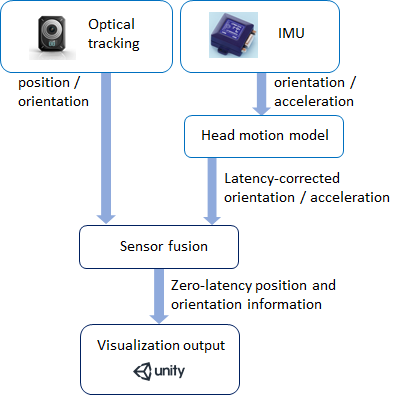
Our locations-based VR / large room-scale tracking solution solves this problem by combining optical tracking information with inertial measurement data using a special predictive algorithm based on a head motion model.
| Compatible HMDs: | HTC VIVE, HTC VIVE Pro |
| Compatible optical tracking systems: | Optitrack, VICON, ART, Qualisys, all VRPN-compatible tracking systems |
| Compatible software: | Unity, Unreal, Autodesk VRED, all SteamVR-compatible applications |
This location-based VR solution is now available from LP-RESEARCH. Please contact us here for more information or a price quotation.
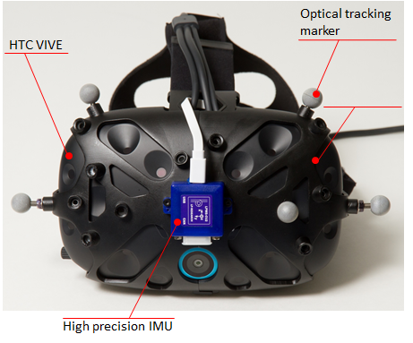
The system follows each HMD using a combination of optical and IMU tracking. A special 3D-printed holder is used to attach a high-quality IMU (LPMS-CU2) and optical markers to an HTC VIVE headset.
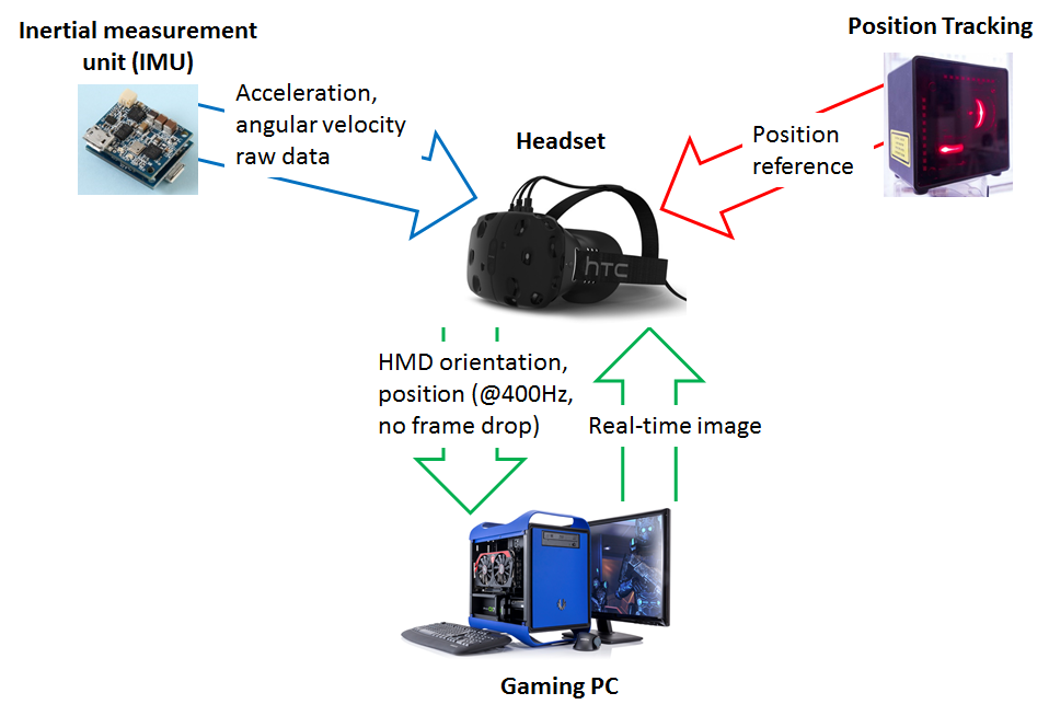
To create a perfectly immersive experience for the user, optical information is augmented with data from an inertial measurement unit at a rate of 800Hz. Additionally to the high frequency / low-latency updates, a head motion model is used to predict future movements of the player’s head. This creates an impression of zero latency gameplay.
In its current configuration the system can track up to 20 actors simultaneously, each holding a VIVE controller to interact with the environment. Players wear backpack PCs to provide visualization and audio.
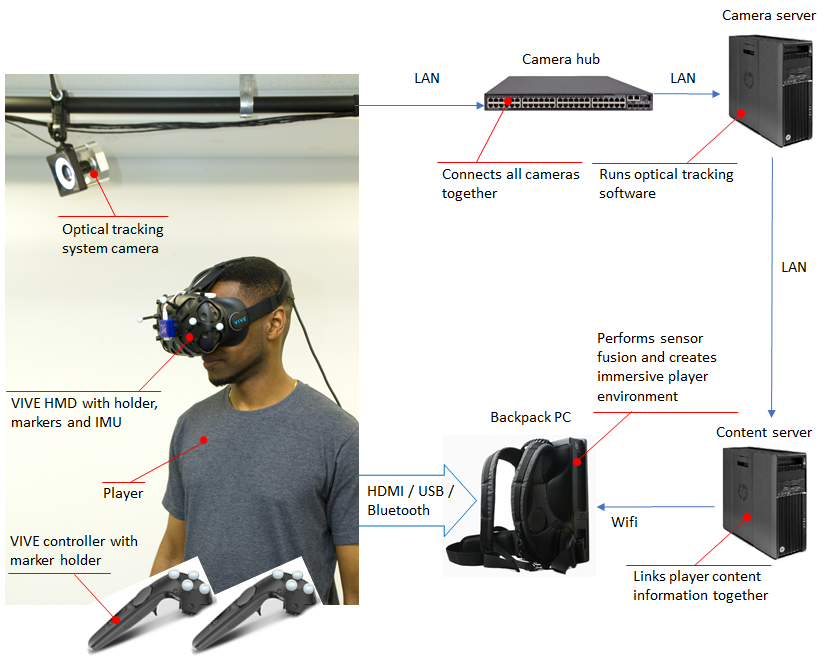
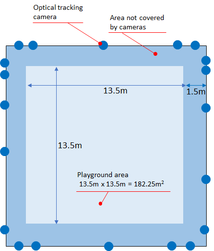
The solution covers an area of 15m x 15m or more. There is an outer border of 1.5m that is out of the detection range of the cameras. This results in an actual, usable playground area of 13.5m x 13.5m. The overall size of the playground is 182.25m². The cameras are grouped around the playground to provide optimum coverage of the complete area.
Contact us for further information.
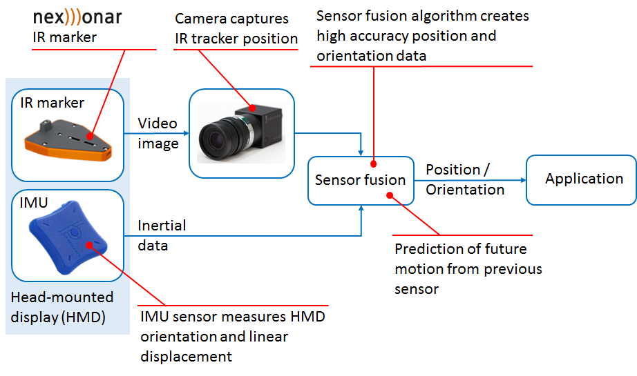
Optical position tracking and inertial orientation tracking are well established measurement methods. Each of these methods has its specific advantages and disadvantages. In this post we show an opto-inertial sensor fusion algorithm that joins the capabilities of both to create a capable system for position and orientation tracking.
The reliability of position and orientation data provided by an optical tracking system (outside-in or inside-out) can for some applications be compromised by occlusions and slow system reaction times. In such cases it makes sense to combine optical tracking data with information from an inertial measurement unit located on the device. Our optical-intertial sensor fusion algorithm implements this functionality for integration with an existing tracking system or for the development of a novel system for a specific application case.
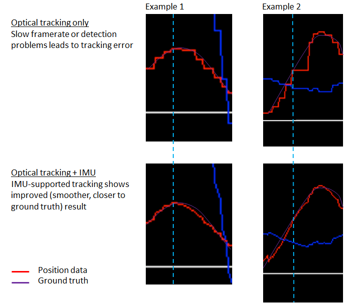
The graphs below show two examples of how the signal from an optical positioning system can be improved using inertial measurements. Slow camera framerates or occasional drop-outs are compensated by information from the integrated inertial measurement unit, improving the overall tracking performance.
For a demonstration, we combined three NEXONAR IR trackers and an LPMS-B2 IMU, mounted together as a hand controller. The system allows position and orientation tracking of the controller with high reliability and accuracy. It combines the strong aspects of outside-in IR tracking with inertial tracking, improving the system’s reaction time and robustness against occlusions.
The tracking of virtual reality (VR) headsets is one important area of application for this method. To keep the user immersed in a virtual environment, high quality head tracking is essential. Using opto-inertial tracking technology, outside-in tracking as well as inside-out camera-only tracking can be significantly improved.
Robot Operating System (ROS) is a tool commonly used in the robotics community to pass data between various subsystems of a robot setup. We at LP-Research are also using it in various projects, and it is actually very familiar to our founders from the time of their PhDs. Inertial Measurement Units are not only a standard tool in robotics, the modern MEMS devices that we are using in our LPMS product line are actually the result of robotics research. So it seemed kind of odd that an important application case for our IMUs was not covered by our LpSensor software: namely, we didn’t provide a ROS driver. We are very happy to tell you that such a driver exists, and we are happy that we don’t have to write it ourselves: the Larics laboratory at the University of Zagreb are avid users of both ROS and our LPMS-U2 sensors. So, naturally, they developed a ROS driver which they provide on their github site. Recently, I had a chance to play with it, and the purpose of this blog post is to share my experiences with you, in order to get you started with ROS and LPMS sensors on your Ubuntu Linux system.
Please check our download page for the latest version of the library, at the time of this writing it is 1.3.5. I downloaded it, and then followed these steps to unpack and install it:
|
1 2 3 4 |
tar xvzf ~/Downloads/LpSensor-1.3.5-Linux-x86-64.tar.gz sudo apt-get install libbluetooth-dev sudo dpkg -i LpSensor-1.3.5-Linux-x86-64/liblpsensor-1.3.5-Linux.deb dpkg -L liblpsensor |
I also installed libbluettoth-dev, because without Bluetooth support, my LPMS-B2 would be fairly useless.
If you don’t already have a working ROS installation, follow the ROS Installation Instructions to get started. If you already have a catkin work space you can of course skip this step, and substitute your own in what follows. The work space is created as follows, note that you run catkin_init_workspace inside the src sub-directory of your work space.
|
1 2 3 |
mkdir -p ~/catkin_ws/src cd !:2 catkin_init_workspace |
We can now download the driver sources from github. It optionally makes use of and additional ROS module by the Larics laboratory which synchronizes time stamps between ROS and the IMU data stream. Therefore, we have to clone two git repositories to obtain all prerequisites for building the driver.
|
1 2 3 |
cd ~/catkin_ws/src git clone https://github.com/larics/timesync_ros.git git clone https://github.com/larics/lpms_imu.git |
That’s it, we are now ready to run catkin_make to get everything compiled and ready. Building was as simple as running catkin_make, but you should setup the ROS environment before that. If you haven’t, here’s how to do that:
|
1 2 3 |
cd ~/catkin_ws source devel/setup.bash catkin_make |
This should go smoothly. Time for a test.
Now that we are set up, we can harness all of the power and flexibility of ROS. I’ll simply show you how to visualize the data using standard ROS tools without any further programming. You will need two virtual terminals. In the first start roscore, if you don’t have it running yet. In the second, we start rqt_plot in order to see the data from our IMU, and the lpms_imu_node which provides it. In the box you can see the command I use to connect to my IMU. You will have to replace the _sensor_model and _port strings with the values corresponding to your device. Maybe it’s worth pointing out that the second parameter is called _port, because for a USB device it would correspond to its virtual serial port (typically /dev/ttyUSB0).
|
1 2 |
rosrun rqt_plot rqt_plot & # Wordpress sometimes (but not always!) inserts "amp;" after the ampersand, if you see it, please ignore it. rosrun lpms_imu lpms_imu_node _sensor_model:="DEVICE_LPMS_B2" _port:="00:04:3E:9E:00:8B" |
Once you enter these commands, you will then see the familiar startup messages of LpSensor as in the screenshot below. As you can see the driver connected to my LPMS-B2 IMU right away. If you cannot connect, maybe Bluetooth is turned off or you didn’t enter the information needed to connect to your IMU. Once you have verified the parameters, you can store them in your launch file or adapt the source code accordingly.
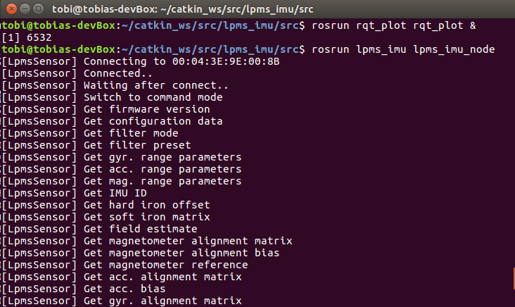
Screenshot of starting the LPMS ROS node
The lpms_imu_node uses the standard IMU and magnetic field message types provided by ROS, and it publishes them on the imu topic. That’s all we need to actually visualize the data in realtime. Below you can see how easy that is in rqt_plot. Not as cool as LpmsControl, but still fairly cool. Can you guess how I moved my IMU?
Please get in touch with us, if you have any questions, or if you found this useful for your own projects.
Update: Martin Günther from the German Research Center for Artificial Intelligence was kind enough to teach me how to pass ROS parameters on the command line. I’ve updated the post accordingly.
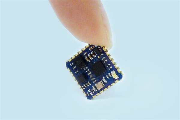
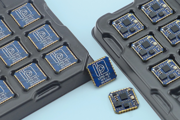
The LPMS-ME1’s Maker Edition is miniature-sized with just 12 x 12 x 2.6 mm.
We proudly present you our latest development! The LPMS-ME1 is our smallest motion sensor so far, with just 12 x 12 x 2.6 mm it is tiny! Despite its size this powerful 9-axis inertial measurement unit (IMU) has several sensors integrated, for example a 3-axis accelerometer, a 3-axis gyroscope and a 3-axis magnetometer. And this miniature motion sensor certainly comes at low cost.
It is very easy to assemble and can be conveniently embedded in the system of your choice. Due to its size it is perfect for your design ideas and development projects. Just to to give you some inspiration, it can be used for human motion capture or sports performance evaluation, for various sorts of Internet of Things (IoT) devices, and can be used to control unmanned aerial vehicles. You can even fly a drone with it!
Have a look at more specifications in our data sheet. This sensor comes with our own LpmsControl utility software and a one-year warranty service.
Get the LPMS-ME1 Maker Edition for your own innovations! Find a distributor of your choice or order online at Zenshin Tech.