LPVR New Release 4.9.2 – Varjo XR-4 Controller Integration and Key Improvements

New release LPVR-CAD and LPVR-DUO 4.9.2

As it is with software, our LPVR-CAD and LPVR-DUO products for high-fidelity VR and AR need maintenance updates. Keeping up-to-date with the wide range of supported hardware as well as fixing issues that are discovered necessitates a release every now and then. Our latest release, LPVR-CAD 4.9.2 and LPVR-DUO 4.9.2 is no different. This blog post summarizes the changes in the latest version, LPVR-CAD 4.9.2 and LPVR-DUO-4.9.2.

Support for Varjo XR-4 Controllers

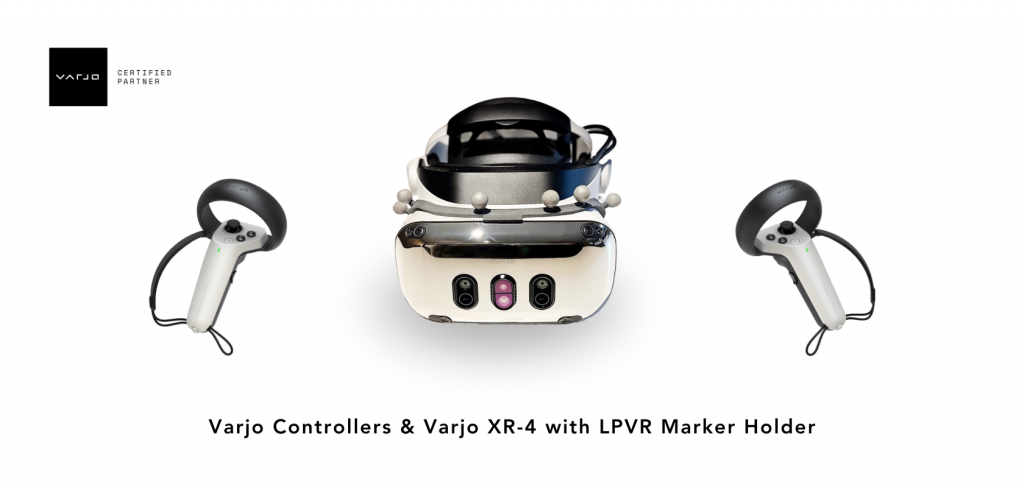
The feature with the highest visibility is support for the hand controllers that Varjo ships with the Varjo XR-4 headset. These controllers are tracked by the headset itself, and Varjo Base 4.4 adds an opt-in way of supporting them with LPVR-CAD. Varjo does not enable the controllers by default because the increased USB traffic can negatively affect performance on some systems, and so an LPVR user has to decide whether the added support is worth it on their system. Of course, we also continue supporting the SteamVR controllers together with LPVR-CAD. We detailed their use with the XR-4 in our documentation.

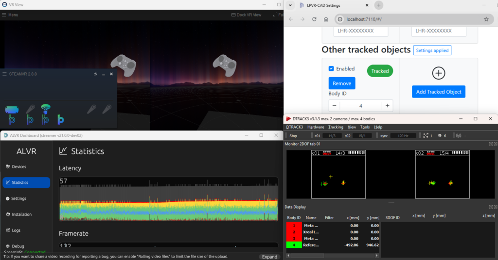
To enable the Varjo controllers in LPVR-CAD, first open Varjo Base. Then navigate to the System tab in Varjo Base. When LPVR-CAD is configured you will find a new input field, depicted below.

Setting its value to “true” will enable controller support, and “false” will disable it. After changing the value, scroll down to the Submit button and click it to effect the change. Varjo also recommends restarting Base after making this change.

Please note that this input is handled by Varjo Base itself, and so this button will also appear in older versions of Varjo Base, for reasons that are too broad to go into here. Providing this support quickly had higher priority to Varjo and us than polish. One issue that can cause confusion is that the Varjo Home screen will not display the controllers, at least in Varjo Base 4.4.0. Unity applications will have to be updated to a recent version of the Varjo plugin. Varjo is working on improving these issues.


Updated Support for JVC HMD-VS1W

An interesting AR headset of see-through type is JVC’s HMD-VS1W. It is a niche product which is typically used in the aeronautical sector. This is a headset which uses Valve tracking with a few custom twists. With a recent software update on their side (version 1.5.0) compatibility with LPVR was broken, but it was easy enough to restore and we have recovered full compatibility.


Various other changes

One of the key points when creating an immersive VR and AR experience is that the motion should appear as smooth as possible. We are therefore constantly refining our algorithms to meet that goal. This release significantly improves the smoothness of rotations, especially for Varjo’s third-generation headsets such as the Varjo Aero and the Varjo XR-3.

We fixed a condition where under some circumstances LPVR-DUO would crash after calibrating the platform IMU. This was related to a multi-threading issue which caused a so-called deadlock in the driver.

We also added support for a global configuration of our SteamVR driver which can be overridden by local users. Since automatic support for this requires major changes to our installers and uninstallers, we decided to postpone enabling this feature by default. Please get in touch if that is something you want to use already.

We often recommended the so-called “freeGravity” feature to our users to improve visual performance in most circumstances. We changed the default for this setting to match the needs for the most common use cases.

FusionHub – Sensor Fusion Operating System

Introduction

In the past years our team at LP-RESEARCH has worked on a number of customer projects that required us to customize our sensor fusion algorithms for a specific application.

Such customization usually doesn’t include significant changes to our existing filter algorithms, but in most cases only warrants changes to input/output interfacing, specialized extensions to the core functionality.

Our own products such as the LPMS inertial measurement units, the LPVR virtual and augmented reality tracking system series and LPVIZ are based to a large extent on the same fundamental algorithms, but with different sensor inputs and different data output interfaces.

For this reason we decided to develop a modular platform that would allow us to create a graph of nodes, each node with a specific functionality as either:

  • Sensor data source (Gyroscope source, GPS etc.)
  • Filter algorithm (IMU-optical filter, odometry-GPS filter etc.)
  • Output sinks (File writer, websocket output, VRPN output etc.)

Modular Platform

This modular platform we call the FusionHub or sensor fusion operating system (SFOS) as it creates an end-to-end solution for applications that need a high performance and flexible sensor input/output and filtering system. FusionHub is platform independent and can run on Windows, Linux and Android. We are also working on a port to Apple’s VisionOS.

One might argue that a very simlar solution exists in the form of the Robot Operating System (ROS). ROS is a powerful platform, but it is relatively large in the amount of base components that it needs to run.

With FusionHub, we rely on the ZeroMQ protocol and Google’s Protocol Buffers for the communication of our nodes. This keeps the application light weight and independent from any other software stack or platform.

Apart from proprietary external libraries that might be needed to connect to certain sensor systems, FusionHub is a standalone application. It easily runs even on embedded hardware systems such as the Meta Quest virtual reality display series.

Easy Configuration

The components of a FusionHub graph are configured using a simple JSON script. For example a sensor input from one of our LPMS-IG1 IMUs is configured as shown below:

"imu": {
	"outEndpoint": "inproc://imu_data_source",
	"settings": {
		"autodetectType": "ig1"
	},
	"type": "OpenZen"
}  

An IMU-optical sensor fusion node would be configured similar to the below script:

"fusion": {
	"dataEndpoint": "inproc://fusion_output",
	"inputEndpoints": [
		"inproc://optical_data_source",
		"inproc://imu_data_source"
	],
	"settings": {
		"SensorFusion": {
			"alignment": {
				"w": 0.464394368797396,
				"x": -0.545272191516426,
				"y": 0.5236543865322006,
				"z": 0.46130487841960544
			},
			"orientationWeight": 0.005,
			"predictionInterval": 0.01,
			"sggPointsEachSide": 5,
			"sggPolynomialOrder": 5,
			"tiltCorrection": null,
			"yawWeight": 0.01
		}
	},
	"type": "ImuOpticalFusion"
}

Each node contains input and output endpoints, or one of the two for source and sink nodes, that allow other nodes to connect to them. Connections can be limited to inside the application (“inproc://..”) or also be accessible from outside the application (“tcp://..”). This allows for constructing node networks that run on distributed machines. For example one computer could acquire data from a specific sensor and another computer could apply a sensor fusion algorithm to the incoming data.

This is also a simple way how additional nodes developed by 3rd parties can communicate with or via the FusionHub.

We have so far created the follwing node components:

Inputs

  • LPMS input node
  • Optical tracking system input node (ART, Optitrack, VICON, Antilatency)
  • (RTK-)GPS input nodes (NMEA, RTCM)
  • Car odometry via CAN bus input node

Outputs

  • File writer node
  • VRPN output node
  • Websocket output node

Filters

  • IMU-optical fusion node (for LPVR systems)
  • GPS-odometry fusion node (for car navigation)
  • RTK-GPS-odoemtry-IMU fusion node (for car navigation)

Future Outlook

With great success we’ve deployed FusionHub for our own products as well as several customer projects.

While our collection of node components and the range of applications for FusionHub is growing, we spend significant development resources on creating testing frameworks that guarantee the performance and robustness of FusionHub. As the application of FusionHub in our LPVIZ driving assistance system is mission critical, reliability and redundancy of our core framework is essential.

In the future we’re looking to connect FusionHub with our internal IoT solution LPIOT to open up access to our core algorithm to large numbers of sensor devices in parallel. Furthermore we are working with machine learning-focused company Archetype AI to give deeper inteligence to this solution.

See further information about how to use FusionHub in the FusionHub documentation.

LPVR-AIR for Immersive Collaborative Industrial Design

Wireless Content Streaming

LPVR-AIR is LP-Research’s wireless VR streaming solution. Content is generated on a rendering computer and wirelessly streamed to a VR headset to be displayed. At the same time the pose, orientation and position, of the headset is calculated from tracking data from a camera system and inertial measurements on the headset itself.

The core tracking algorithm of LPVR-AIR is similar to our LPVR-CAD solution. We are combining this established tracking method with wireless data streaming.

This has a few significant advantages:

  • Rendering detailed VR content is computationally too heavy to do all calculations on embedded hardware on the headset itself. Therefore, content needs to be rendered on an external computer and the result is streamed to the headset. LPVR-AIR allows doing this.
  • Designers in eg. the automotive space have their own preference of applications to create content, such as Autodesk VRED. These applications usually don’t run on a headset’s embedded hardware. With LPVR-AIR dsigners can use any application that normally works with a Windows based PC.

Technical Implementation

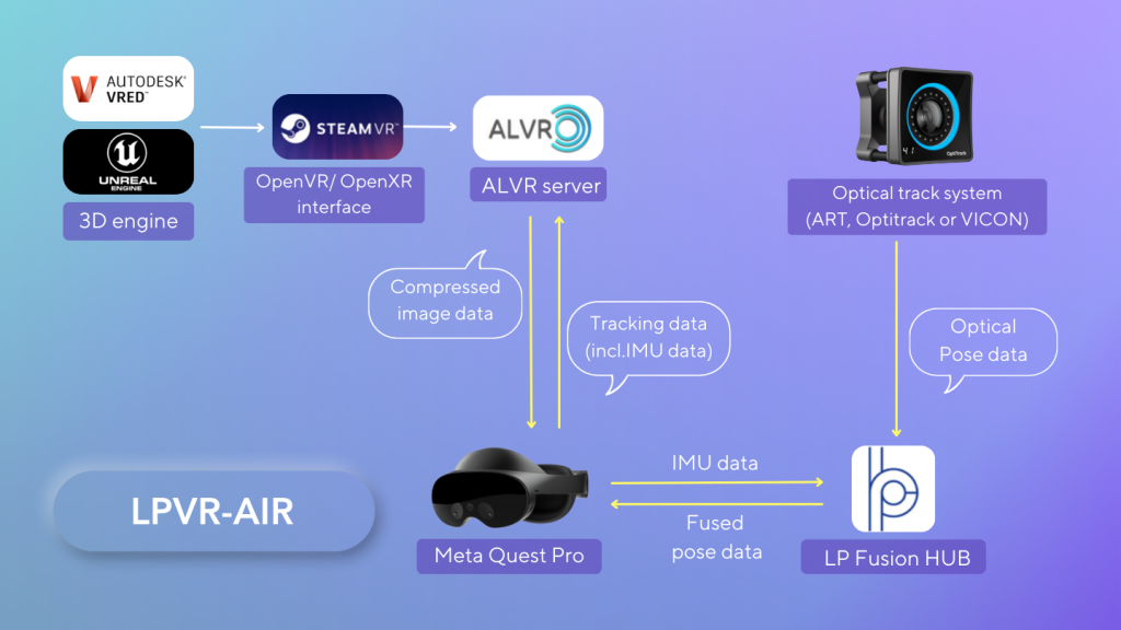
See below a block diagram of how the LPVR-AIR system is implemented. While we in principle support any Android based standalone VR headset, we currently focus on the Meta Quest line of HMDs, specifically Meta Quest Pro and Meta Quest 3.

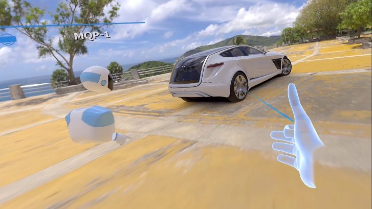
Our solution effectively enables designers to explore a large 3D design space with full high resolution renderings using a lightweight headset. LPVR-AIR even allows for the interaction of several users in a design space. An example of such a use case is shown in the video on the top of this post. Two users in our office in Tokyo, being tracked by LPVR tracking, explore a car design together.

Improved Design Process

This opens new possibilities for automotive, industrial, architecture and many more design applications, leading to increased performance of designers and a higher success rate of their designs. LPVR-AIR is based on the ALVR wireless streaming engine, which we have extended to work with our FusionHub sensor fusion solution.

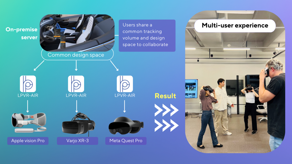
Long term, the ALVR engine makes it easy for us to support a number of different HMDs, additionally to Meta Quest also the Varjo and eventually the Apple Vision Pro series as shown in the image below. With VRED we have an outstanding rendering solution at the base of LPVR-AIR that allows designers to create photo-realistic content while providing extensive collaboration abilities.

If you would like to move towards immersive and interactive 3D design, don’t hesitate to consult with us and give our LPVR-AIR on-premise collaborative design solution a try!

Immersive Driving Assistance with LPVIZ

How LPVIZ Augments Driving Reality

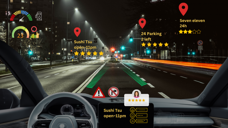
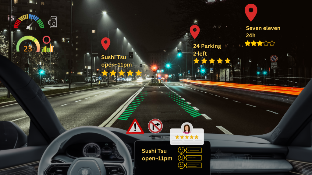
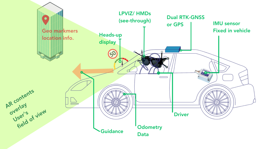
Going beyond a simple screen replacement, LPVIZ is an augmented reality driving assistance solution for the car. It allows displaying related content to a driver or passenger in 3D, superimposed to reality. Content can be placed anywhere inside the car, such as a virtual speedometer over the dashboard, and anywhere outside of the car, such as point-of-interest markers or navigation guidance.

The video on top of this post shows what a drive around the block in Azabujuban, Tokyo with LPVIZ looks like. A virtual dashboard is projected onto the center console of the vehicle. Arrows on the ground show lane guidance to the driver. Red Google Maps-style markers show points of interest. The virtual dashboard stays fixed to the same location in the car, even when the vehicle turns. The navigation arrows move smoothly and the point-of-interest markers are globally anchored.

Perfectly Tuned Components

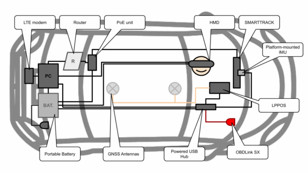
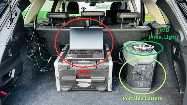
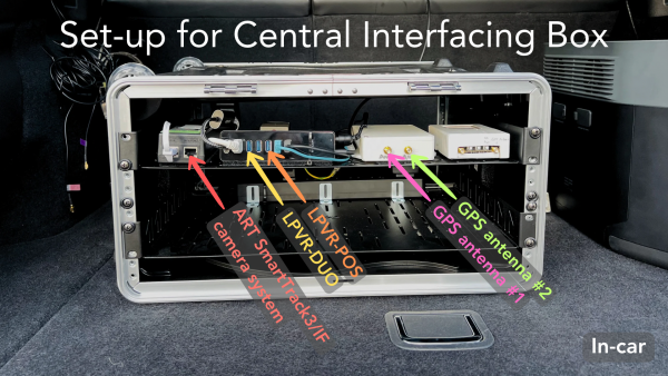
LPVIZ consists of several components that all have to interact perfectly to create a compelling and safe augmentation experience. The below illustration shows a block diagram of how the hardware components are connected.

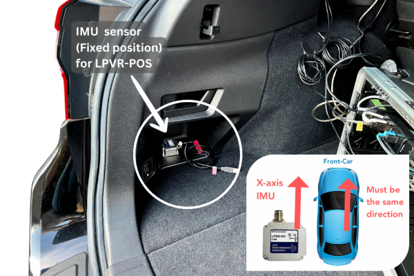
Accurate tracking is required to display useful content to the driver: the HMD pose in the local car coordinate system and the vehicle pose in a globally anchored frame. Precise calibration of all components of the solution is essential to provide the highest visual fidelity and driver safety. Our LPVIZ product makes all parts of the system available in a compact form factor, ready to be integrated with any vehicle.

The Past, Present and the Future

In the current development stage we’re focusing on the most essential aspects of the solution: displaying a virtual dashboard, navigation information and points-of-interest. While this is our proprietary content, we’re opening our software to work with 3rd party developers to create their own content building on our platform.

Currently we’re offering LPVIZ as a B2B solution for prototyping, design and research. However, we’re working on reducing system complexity to make it work as a consumer facing automotive after-market solution to be released later this year.

Towards a Consumer Product

We are very proud of the progress our team has made in the past months. We’re moving closer to making our vision of an augmented reality driving assistance system a reality for everyone. One very important take-away from our recent developments is that it’s indeed possible to provide real utility to the driver using technology that is readily available. It might still be early days, but we’re edging towards a product that could appeal to a wider consumer market. This is just the beginning.

LPVR-DUO in an Airborne Helicopter

In-Flight VR

Imagine soaring through the skies as a pilot, testing the limits of a helicopter’s capabilities while feeling the rush of wind and turbulence. Now imagine that you don’t see the real world outside and the safe landing pad that your helicopter is approaching but a virtual reality (VR) scene where you are homing in on a ship in high seas. The National Research Council Canada (NRC) and Defence Research and Development Canada (DRDC) have brought this experience to life with their groundbreaking Integrated Reality In-Flight Simulation (IRIS).

IRIS is not your ordinary simulator; for one, it’s not sitting on a hexapod, it’s airborne. It’s a variable-stability helicopter based on the Bell 412 that can behave like other aircraft and can simulate varying weather conditions; combine that with a VR environment and you have a tool that allows safely training operations in the most adverse conditions. In particular it is used for Ship Helicopter Operating Limitations (SHOL) testing.

Mission-Critical Application with LPVR-DUO

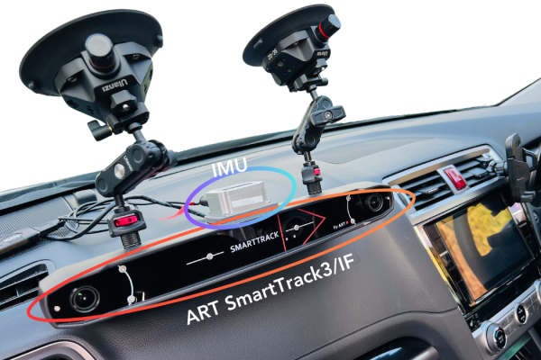
The LPVR-DUO system is what makes VR possible on this constantly moving platform. This cutting-edge AR/VR tracking system seamlessly merges the inertial measurements taken by the headset with the helicopter’s motion data and a camera system mounted inside the cabin to provide the correct visuals to the pilot. The challenges of using cameras to track the VR headset inside the tight environment of the helicopter while lighting conditions are ever-changing are overcome by using an ART SmartTrack 3 system. This system follows an arrangement of reflective markers attached to the pilot’s helmet. The VR headset is attached to the helmet in such a way that the pilot can wear it as if it were a pair of night vision goggles. Put together, this allows displaying a virtual world to the pilot, even in the most extreme maneuvers.

To ensure an authentic experience, the IRIS system incorporates real-time turbulence models, meticulously crafted from wind tunnel trials. These turbulence effects are seamlessly integrated into the aircraft’s motion and into the VR scene, providing pilots with precise proprioceptive and vestibular cues. It’s a symphony of technology and innovation in the world of aviation testing.

In-Cockpit Implementation

The optical tracking system relies on highly reflective marker targets on the helmet to track movement in three dimensions. Initially, only five markers were installed, strategically placed for optimal tracking. But the pursuit of perfection led NRC to create custom 3D-printed low-reflectivity helmet molds, allowing them to mount a dozen small passive markers. This significantly improved tracking reliability in various lighting conditions and allowed for a wider range of head movement.

Recently, NRC put this remarkable concept to the test with actual flight trials. The response from pilots was nothing short of exhilarating. They found the system required minimal adaptation, exhibited no noticeable lag, and, perhaps most impressively, didn’t induce any motion sickness. Even the turbulence effects felt incredibly realistic. Surprisingly, the typical VR drawbacks, such as resolution and field of view limitations, had minimal impact, especially during close-in shipboard operations. It’s safe to say that IRIS has set a new standard for effective and immersive aviation testing.

Publication of Results

The NRC team presented their results at the Vertical Flight Society’s 79th Annual Form in two papers [1] and [2] and they also have a blog post on their site.

NOTE: Image contents courtesy of Aerospace Research Centre, National Research Council of Canada (NRC) – Ottawa, ON, Canada

1 2 3 7